


beta
|
||||||
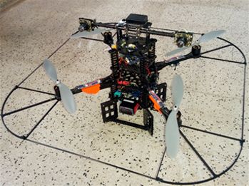 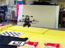 Figure 1: A quodrotor is hoovering based on visual feedback
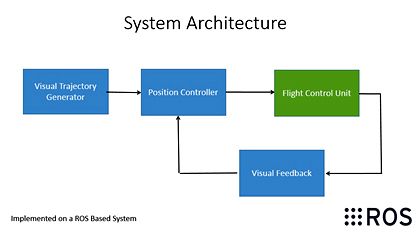 Figure 2: System architecture for Vision Based Navigation
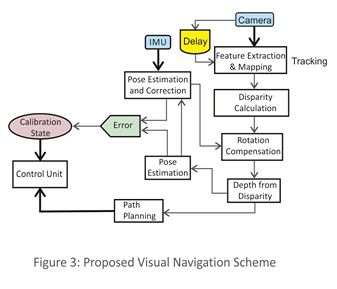 Figure 3: Proposed Visual Navigation Scheme
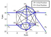 Figure 4: Six agents make a formation
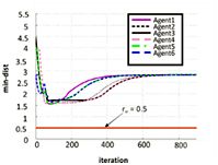 Figure 5: There is no collision during the formation
 Figure 6: Temporal Evolution of the boundary
 Figure 7: Convergence of the agents to the boundary
|
The need for unmanned aerial vehicles (UAVs) with greater maneuverability and hovering ability for various military and civilian applications has led to the current rise in quadrotor research. A quadrotor, also called a quadrotor helicopter or quadcopter, is a multi-copter that is lifted and propelled by four rotors. The four-rotor design allows quadrotors to be relatively simple in design yet highly reliable, agile and maneuverable.
The concept of Localization is used for maintaining the quadrotor at a particular point in 3Dspace. In Figure 1, we demonstrate visual control of a quadrotor (Pelican from AscTec) for hovering at a specific altitude where the current position is obtained by looking at a predefined
Single camera is used to reduce the payload and increase the endurance of the system. The two frames, displaced in time, are taken to simulate the stereo vision for computing the depth of the target/scene. To calculate the correspondence between two frames, feature points detected from the images are matched. We can calculate the disparity between matched points caused by UAV movement by taking the difference between the two coordinate positions in the scenes. Since the UAV can also undergo rotation, we compensate for disparity caused by rotation. The scheme is provided in Figure 3.
Formation of quadrotors has great applications in precision agriculture, disaster management and crowd control. We consider an n-agent system where the agents move on a plane. Each agent communicates with its neighbours. The communication topology is fixed and is represented by a completely connected graph G. The objective of this work is to develop a control law to achieve a desired formation. The control law comprises of two parts: Improve collision avoidance scheme (ICAS) and consensus term. The ICAS has been designed to avoid collision between agents, and the consensus term helps in achieving the desired formation.
We consider 2n-agent system where the agents move on a plane. Each ith agent can communicate with its two neighbouring agents (Backward and Forward agents). The communication topology is fixed and is represented by a connected graph G. Each ith actual agent is associated with (i+1)th virtual agent (odd index is for actual agents and even index is for the corresponding virtual agent). The objective of this work is to develop a boundary tracking and estimation algorithm to track the static and dynamic boundary. In this work we are assuming that velocity of the dynamic boundary is less than the agent's velocity.
|
|||||


