| |
Manufacturing Science Lab
Teaching Laboratory
ME 361A: Manufacturing Technology
Overview:
Objective of this course is to give a broad understanding of conventional and non-conventional machining processes with an emphasis on the characterization techniques. This course also familiarizes students with the scientific principles governing various machining processes.
Equipments
- On Lathe- Lab VIEW Software, Three-component piezo-crystal type dynamometer make Kistler, NI DAQ Card, Microbalance, Dinolite USB Microscope, Vernier Calliper e.t.c.
- On Grinding- Lab VIEW Software, Three-component piezo-crystal type dynamometer make Kistler, NI DAQ Card, Microbalance, Dinolite USB Microscope, Portable Surface Roughness Measuring Instrument etc.
- On EDM – Electronica ZNC EDM Machine, Microbalance, Shadowgraph/ USB Microscope, Micrometer, Stopwatch, etc.
- On Hydraulic Press- USB Microscope, Load Cell, Lab VIEW Software, NI DAQ Card, Vernier Calliper, Proving Ring etc.
- On Microchannels fabrication- Microbalance, USB Microscope, Dessicator, vacuum pump, Furnace temperature upto 400 degree centigrade etc.
- On Milling- Multi-component dynamometer make Kistler, Labview software, NI DAQ Card, Dinolite USB Microscope, Vernier Calliper, Microbalance etc.
Experiments:
- To measure the cutting force, tool temperature and shear angle during orthogonal cutting (on Lathe).
- To study the effects of grinding variables on grinding forces, specific energy and surface finish.
- To study the EDM machine and determine material removal rate and tool wear rate during machining of EN8 steel.
- To draw a cup by cup drawing process and measure the drawing force on hydraulic press.
- To fabricate micro channels through micro Replication double inversion technique.
- Investigation of wear and cutting processes (Fx, Fy, Fz and Mz) near the tool age during milling and drilling by Rotating 4-Component Dynamometer (RCD) on EMCO Mill concept 250.
- To obtain the measurement of a given component using coordinate measuring machine (CMM).
- To fabricate micro channel through epilog laser fiber mark fusion engraving machine.
- To measure the axial force, with tool speed for different diameters, if the feed is constant on HMT Radial Drill Machine.
- To obtain the measurement of roundness of a given component using Out of roundness measuring machine (Mitutoyo, Japan)
- To measure the cutting force, shear angle during orthogonal cutting, cnc programming (Absolute/Incremental) and operations on flat bed Simple Turn5075 ACE Designer CNC Lathe Machine.
- To study the various features of surface roughness measuring instrument also measure the parameters of the specimen.
- To study the integrated multi process (µ-milling, µ-turning, µ -drilling, µ-EDM, µ-ECM, µ-wire cut, µ-EDG) on micromachining machine DT-110.
|
Processing Equipment:
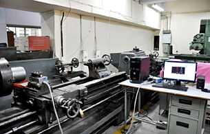
HMT LB-25 Centre Lathe:
Specification:
HMT LB-25 LATHE 500mm SWING x 2000mm BETWEEN CENTRES. 18 SPEEDS 32-1600 RPM. 52mm SPINDLE BORE WITH 3 JAW CHUCK, 4 JAW CHUCK, FACE PLATE, MULTIFIX QUICK CHANGE TOOLPOST.
|
|
|
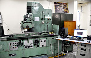
Processing Equipment:
Horizontal Surface Grinding Machine
Make: HMT
Model: SFW1
Magnetic Chuck Size: 1000mm x 300mm
Accuracy: 2 μm
Table speed: 2.5, 5, 10, 15, 20, 25 (m/min)
RPM: 1500
|
|
|
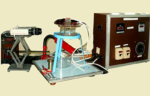
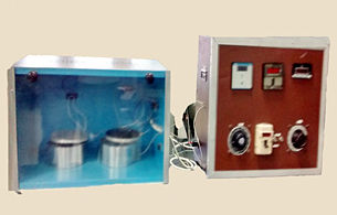
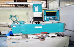
Processing Equipment:
Electronica R50# ZNC
Work tank : 800 x 500 x 350 mm
Work table size: X Y Z : 300 x 250 x 200 mm
Programmable Z axis control, manually operated x and y axis.
Accuracy: 5µ
99 programs, 50 steps per program
Max. working current: 50A
Gap voltage: 100-270V
Max. Stock removal (cu-steel): 300(cu.mm/min)
Best surface finish: 0.5µ CLA
Electrode wear: 0.3-20%
|
|
|
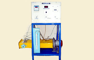
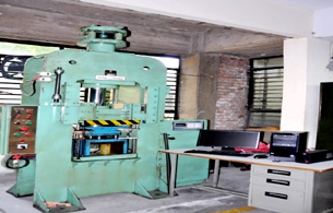
Processing Equipment:
SPECIFICATION:
Make : Fluid Power
Type : Hydraulic
Bed Size : 500 mm x 500 mm
RAM Dia. : 12 mm"
Capacity : 10 T
|
|
|
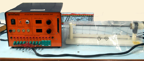
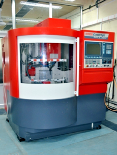
Processing Equipment:
SPECIFICATION:
Model/Make: EMCO Concept Mill 250
Max Speed: 10,000RPM, Power 7KW
20 Station Tool Drum with directional logic
Travel- X350mm, Y250mm, Z300mm
Clamping Surface- 500x300mm
PC Controlled CNC –Machining center with Interchangeable control
EMCO Software Win NC
SINUMERIK 810/840D machine license (32bit)
Software EMCO 3D View
4th Axis- NC Dividing Head WALTER TANI 80 NEG
5th Axes- Turntable DSE25 èSpindle Speed A axis 15rpm; Spindle Speed B axis 3rpm; Size- X/Y/Z = 520/260/150; Swiveling Height =80MM; Swiveling Area of 4th Axis = Max. ±91o
ESPRIT CAM Software è Powerful Spectrum Programming for
2-5 Axis Milling,
2-22 Axis Turning, 2-5 Axis Wire EDM,
Multitasking Mill Turn Machining,
Swiss Turn and B-Axis Machine Tools High Speed 3 and 5- Axes Machining.
|
|
|
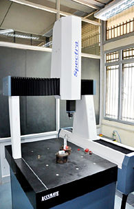
Characterization Equipment:
Coordinate Measuring Machine
Model: - Spectra 5.6.4. CNC
Scale Regulation = 0.5 μm
Machine accuracy = (± 2.5 + L/250) μm; (L: Standard length in mm)
Angular accuracy = 1” (One second)
Granite flatness = 2 micron per meter square
Granite grade = zero grade
Probing system = MS2DI
M/c version = CNC version
M/c working volume = X = 500 mm; Y = 600 mm; Z = 400 mm
Controller name = Renishaw UCC (Universal CMM Controller) lite-2 (U.K.)
|
|
|
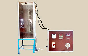
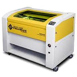
Processing Equipment:
Epilog FiberMark Fusion
Size (W x D x H): 52.5" x 33.5" x 40.75"
(1334 x 851 x 1035 mm)
Engraving Area: 32" x 20"
(812 x 508 mm)
Focal Length (F-Theta Lens): 5" (127 mm)
Maximum Material Thickness: 11.25" (285 mm)
Laser Wattage 20, 30, or 50 watts
Laser Type: Solid State Pulsed Ytterbium Fiber Laser (air cooled)
Mode of Operation: Pulsed 20-80 kHZ.
|
|
| |
|
|
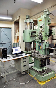
Processing Equipment:
Hindustan Radial Drill Machine
Specification:
Make : HMT
Model : RM61
Spindle Capacity : 60 mm
Arm Length : 1200mm
RPM : 40,56, 80, 112, 150, 220, 300, 440, 580,
850, 1160, 1700
|
|
|
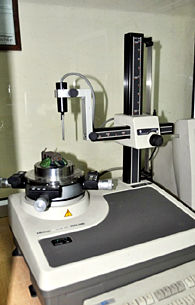
Characterization Equipment:
Mitutoyo RA-116 Round Test
Specification:
• Measuring and analysis software package ROUNDPAK running under Windows operating system
• Air-bearing turntable for high precision, wear-free rotation
• Accepts workpieces up to ø17.32" (440mm) diameter
• Turntable loading 20 kgf maximum
• Measurable diameter ø11.02" (280mm)
• Measuring range ±1000μm
• Measuring height for outside/inside diameters: 11.02" (280mm) maximum
• Measuring depth inside 3.94" (100mm) maximum (with standard stylus)
• Traverse of R axis 6.5" (165mm)
• Large centering range ±.12" (±3mm)
• Large levelling range ±1°
|
|
|
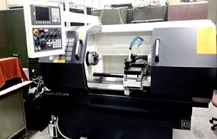
Processing Equipment:
ACE MAKE FLAT BED CNC LATHE MACHINE MODEL SIMPLE TURN 5075 WITH FANUC Oi MATE –TD CONTROL
Specification:
Swing Over Bed: Ø500
Swing Over the cross slide: Ø220
Maximum Turning Length : 650mm
Distance between Centers: 750mm
Spindle speed: 0-4000rpm
Spindle Motor Power: 11/7.5KW
LINEAR TOOLING
X Axis: 300mm
Z Axis: 700mm
Tailstock Quill Travel 180mm
Quill Taper: MT-5
|
|
|
Characterization Equipment:
Surface Roughness Measuring Instrument Specification:
Model SJ–301, Make: Mitutoyo
Measuring range
Z-axis 350 μm
X-axis 12.5 mm
Drive Unit Measuring: 0.25 mm/s; 0.5 mm/s
Speed Returning: 1.0 mm/s
Standard Probe (178-395)
Measuring Method Induction method
Stylus Diamond Tip: Radius 2 μm
Measuring Force 0.75 mN
Parameters: Ra, Rq, Rz
Cut-off-Length: 0.08 mm, 0.25 mm, 0.8 mm,
2.5 mm, 8 mm
Sampling Length: x 1, x 3, x 5, x L
|
|
|
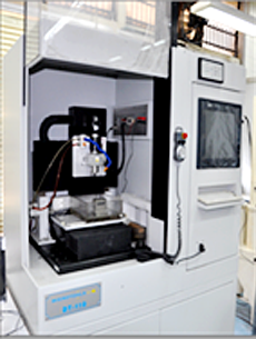
Processing Equipment:
Mikrotools DT-110
Specification:
Work Table: 440 X 320
X & Y Axis Travel: 350 X 270
Z Axis Travel : 320+300
Max weight of the work piece: 350 kg
Work tank: 800 X 480mm
Connected load: 2 KVA
Max matching current: 20 amp.
Machine Footprint: 950 X 770 X 1950
Accuracy: 0.1 μm (100nm).
|
|
|
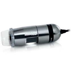
Characterization Equipment:
Dino-Lite Premier USB Microscope
Specification:
Model: AM7013MZT4 Dino-Lite Premier
Interface: USB2.0
Resolution: 5Megapixel
Magnification Range: 20x-250x
Sensor: Color CMOS
Save Formats:
Image: BMP, GIF, PNG, MNG, TIF, TGA, PCX, WBMP, JP2, JPC, JPG, PGX, RAS, PNM DinoXcope: PNG, JPEG
Movie: WMV, FLV, SWF
DinoXcope: MOV
Polarizer and Measurement Function
|
|
| |
|
|
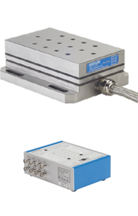
Characterization Equipment:
3-Component Dynamometer
Specification:
Dynamometer with handy size. Built-in charge amplifier with 4 measuring ranges switchable. Simple operation with control unit Type 5233A1.
Type 9257BA
External control unit for range selection and reset/operate. Signal output with 3 x BNC neg. and D-Sub 37-pin.
Type: piezo-crystal
Forces: Fx, Fy and Fz with four miniature
Range: Fx and Fy 500N to 5KN
Fz: 1KN to 10KN
|
|
|
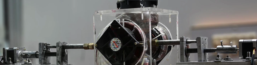
Characterization Equipment:
Rotating 4-Component Dynamometer (RCD)
Specification:
Make: KISTLER
Dynamometer Type 9123C
The dynamometer consists of a four component sensor fitted under high preload between a baseplate and top plate. The four components are measured practically without displacement.
Rotating 4-component dynamometer for measuring of cutting forces and torques on the rotating tool spindle. Transmission of measured data by telemetry hence without wear.
Speed 1/min max. 10 000
Range 1 FSO Fx, Fy kN –5 ... 5
–3 ... 3
Fz kN –20 ... 20
Mz Nm –200 ... 200
Range 2 FSO (switchable) Fx, Fy N –500 ... 500
Fz kN –2 ... 2
Mz Nm –20 ... 20
Sensitivity (Range 1) Fx, Fy mV/N ≈ 2
Fz mV/N ≈ 0,5
Mz mV/Nm ≈ 50
Forces: Fx, Fy, Fz and Mz
|
.jpg)
-2.jpg)
|
|
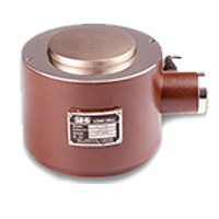
Characterization Equipment:
Column Load Cell
Specification:
Make: IPA
Model: FC074H0
Type: Stain gauge based
Capacity: 70Ton
Gauge Resistance: 350 ohms nominal
Exitation voltage: 10v DC
Sensitivity: 1.5mV/V
Safe overload: 150% of rated load.
Resolution: 50Kg
|
|
|
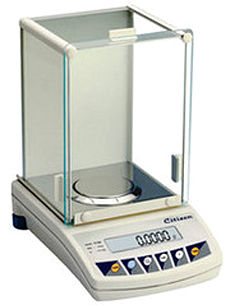
Characterization Equipment: Microbalance
Specification:
Make: CITIZEN
Model: CY204
Capacity x Resolution (g): 220 g x 0.0001 g
Repeatability: 0.0001 g
Linearity: 0.0002 g
Response Time: 2 - 3 seconds
Units: g, mg, ct, GN, mo, oz, dwt
Platform Dimensions: 3.5" diameter
Sensor Type: Electromagnetic Force Compensation
|
|
|
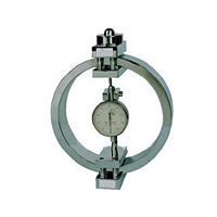
Characterization Equipment:
Proving Ring
Specification:
Make: HEICO
Model: PR-302
Capacity: 5KN
Dial Gauge: ASAHI
Calibrated in: Compression
|
|
|
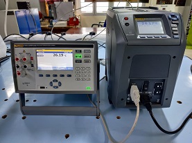
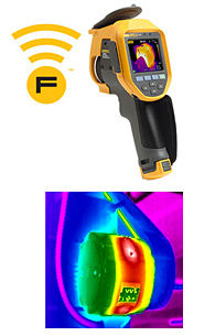
Characterization Equipment:
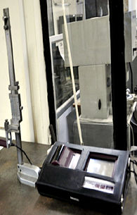
Fluke Ti400 Infrared Camera
Specification:
Make: FLUKE USA
Model: TI-400
Temperature measurement range : -20 °C to +1200 °C
Temperature measurement accuracy: ± 2 °C
Image capture frequency: 9 Hz refresh rate or 60 Hz refresh rate depending upon model variation
Detector type: Focal Plane Array, uncooled microbolometer, 320 x 240 pixels
Thermal sensitivity (NETD): ≤ 0.05 °C at 30 °C target temp (50 mK)
Total pixels: 76800
Minimum focus distance: 15cm
|
|
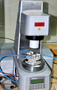
Characterization Equipment:Anton Paar Physica MCR301
Specification:
|
Technical Data
|
Unit
|
MCR 302
|
|
Bearing
|
|
Air
|
|
EC motor
|
|
Yes
|
|
Maximum torque
|
mNm
|
200
|
|
Min. torque, rotation
|
nNm
|
1
|
|
Min. torque, oscillation
|
nNm
|
0.5
|
|
Angular deflection
(set value)
|
µrad
|
0.05 to ∞
|
|
Min. angular velocity
|
rad/s
|
10-9
|
|
Max. angular velocity
|
rad/s
|
314
|
|
Max. speed
|
1/min
|
3000
|
|
Min. angular frequency
|
rad/s
|
10-7
|
|
Max. angular frequency
|
rad/s
|
628
|
|
Normal force range
|
N
|
0.005-50
|
|
Normal force resolution
|
mN
|
0.5
|
|
Max. temperature range
|
°C
|
-150 to +1000
|
| |
|
|
| |
|
|
| |
|
|
| |
|
|
| |
|
|
| |
|
|
| |
|
|
|
|
| |
|
| |
|
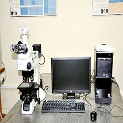
Characterization Equipment:
Nikon eclipse LV100 Industrial Microscope
Specification:
Model name: ECLIPSE LV100D
Magnification: 5x0.15, 10x0.30,
20x0.45, 50x0.80, 100x0.90 (LO plan fluor)
Optical system: CFI60 optical system
Illumination: Lamp ratings: 12 VDC, 50 W halogen lamp
Specified lamp: LV-HL50W 12V 50W halogen lamp
Specified lamp house: LV-LH50PC
Focusing mechanism: Stroke: 30 mm
Coarse focus knob: 14 mm/revolution
Fine focus knob: 0.1 mm/revolution
Eyepiece: 10x, field number: 22, 25
Operating environment: Temp: 0°C to +40°C
Relative humidity: 85% RH max.
Altitude: 2000 m max.
Pollution degree: Degree 2 |
|
Relevant Information (if any): Faculty: Dr. J. Ramkumar (Lab Coordinator) Staff: Mr. Sanjeev Kumar Verma, Mr. Atul Kumar Gangwar Contact Person: Mr. Sanjeev Kumar Verma Location: NL-1-115A Manufacturing Science Lab., ME, IIT Kanpur Phone: 0512-259-7923 Email:
This email address is being protected from spambots. You need JavaScript enabled to view it.
|
|