Features
A Phasor Measurement Unit (PMU) is a device, which measures the electrical waves on an electricity grid, using a common time source for synchronization. PMU technology provides phasor information (both magnitude and phase angle) in real time. A PMU can be a dedicated device, or the PMU function can be incorporated into a protective relay or other device. Time synchronization allows synchronized real-time measurements of multiple remote measurement points on the grid. The advantage of referring phase angle to a global reference time is helpful in capturing the wide area snap shot of the power system. Effective utilization of this technology is very useful in getting the real time behavior of the power system. To study the real-time perfomance of various algorithms developed to improve the system performace, using the real time simulation facility, few PMUs are made available in the laboratory. Typical specifications of the various PMUs available in laboratory are furnished below.
- Measurement defined in IEEE C37.118
- Phasor measurement units (PMU’s) provide information about the voltage and current at point of the network in the form of phasors.
SEL - 421
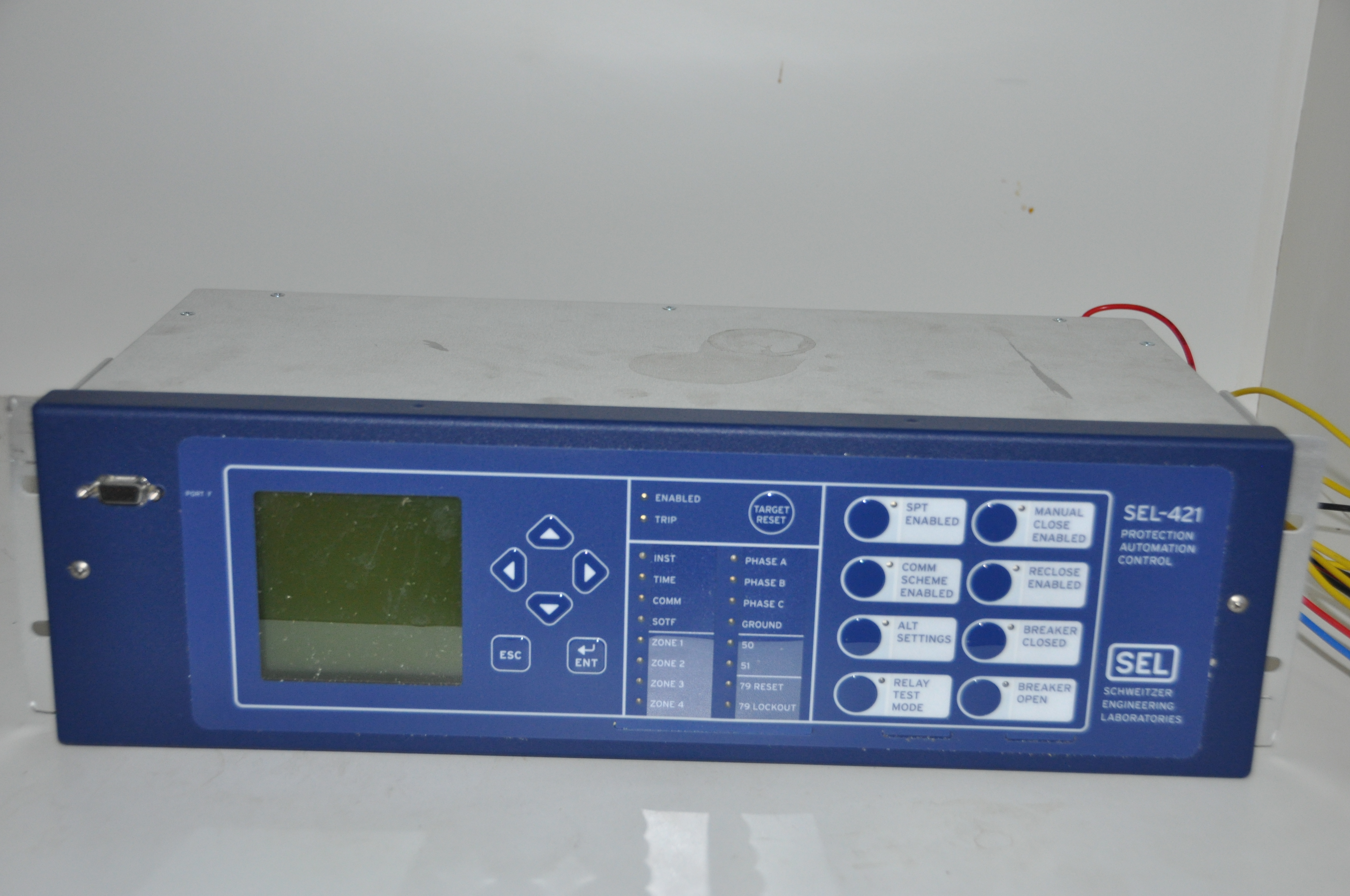 SEL-421 Relay is useful for single- and three-pole tripping schemes, compensated lines, or
uncompensated
lines. Protect transmission lines using five zones of phase and ground-distance elements in
communications-assisted schemes, with directional over current backup protection.
SEL-421 Relay is useful for single- and three-pole tripping schemes, compensated lines, or
uncompensated
lines. Protect transmission lines using five zones of phase and ground-distance elements in
communications-assisted schemes, with directional over current backup protection.
General Specification
| AC Current Inputs |
|
| AC Voltage Inputs |
|
| Serial communications ports |
|
| Ethernet communications |
|
| Synchrophasors |
|
SEL - 451
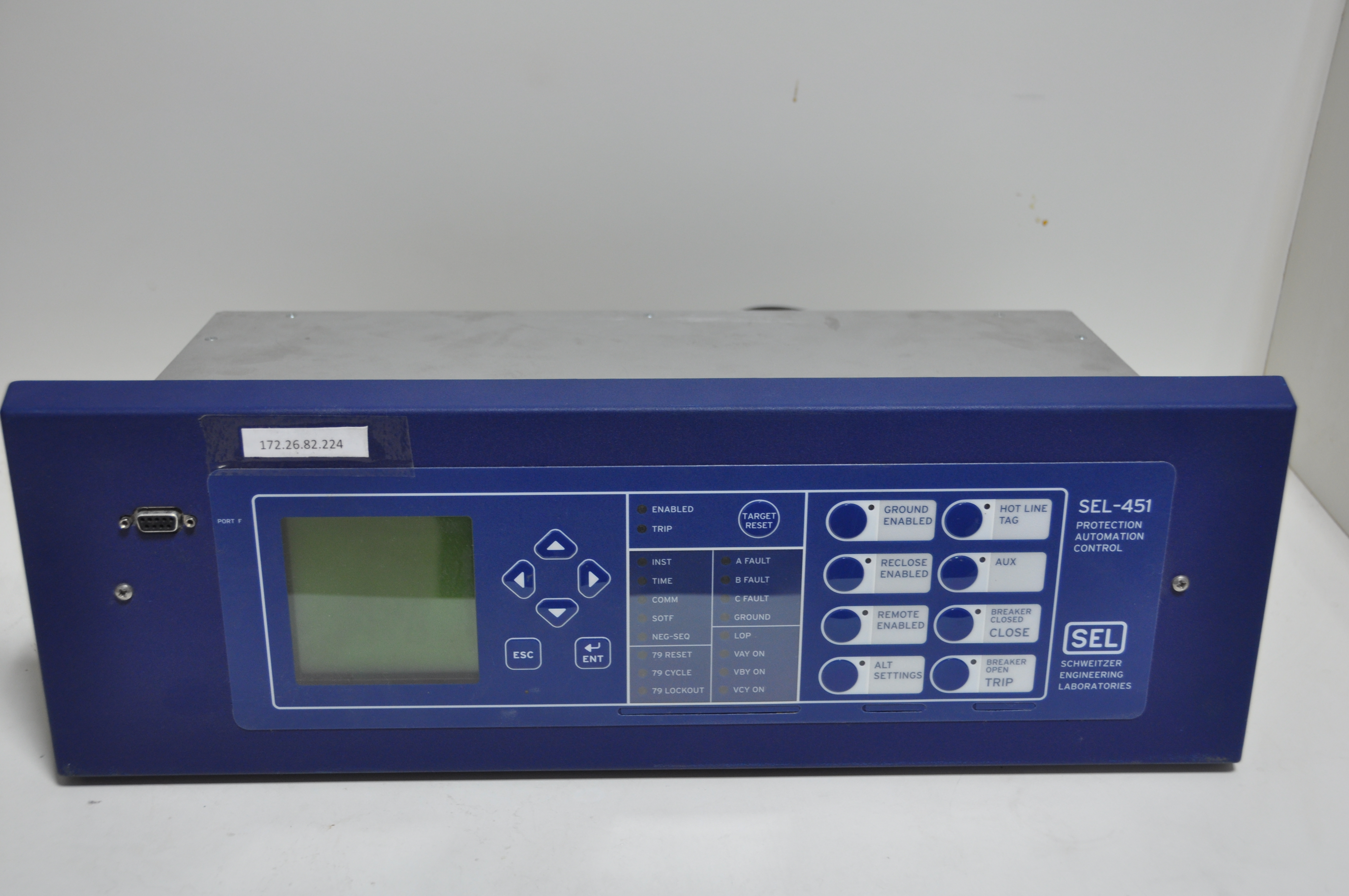 SEL-451 is useful to apply over-current protection for primary and backup, and three-pole
tripping schemes on sub-transmission
lines. It can make settings for up to four shots of automatic breaker reclosing for one or
two circuit breakers, with synchronism
and voltage checks to optimize system restoration. Built-in fault locator is useful to
efficiently dispatch line inspection and repair personnel.
SEL-451 is useful to apply over-current protection for primary and backup, and three-pole
tripping schemes on sub-transmission
lines. It can make settings for up to four shots of automatic breaker reclosing for one or
two circuit breakers, with synchronism
and voltage checks to optimize system restoration. Built-in fault locator is useful to
efficiently dispatch line inspection and repair personnel.
General Specifications
| AC Current Inputs |
|
| AC Voltage Inputs |
|
| Serial communications ports |
|
| Ethernet communications |
|
| Synchrophasors |
|
Arbiter 1133A

Arbiter make, Model 1133A Power Sentinel™ merges precision time synchronization and power measurement features into a single PMU compatible device. It is capable of Measuring the system voltage and current magnitude, phase angle, frequency and time deviations, and tackle revenue metering challenges from a single unit. It also provides the power quality measurement information, like flicker, harmonics, interruptions, etc.
General Specifications
| AC Current Inputs |
|
| AC Voltage Inputs |
|
| Serial communications ports |
|
| Ethernet communications |
|
| Synchrophasors |
|
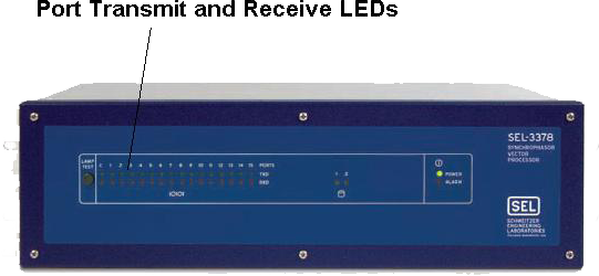
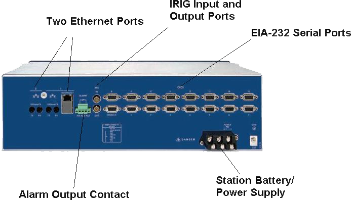
Phasor Data Concentrator (PDC) receives data from various PMUs and consolidates their phasor data for wide area monitoring and control. Hardware PDC (SEL-3378 from SEL) is capable of communicating with as many as 15 devices serially and some more can be interfaced using Ethernet port. In addition to the hardware PDC available in the laboratory, software PDC such as openPDC (an open source software) is also used to consolidate the phasor data. Brief description about the specifications of the SEL-3378 is presented below.
SEL-3378 Synchrophasor Vector Processor
General Specifications
| Serial Communication |
|
| Ethernet communication |
|
| Synchrophasors |
|
| Processing Capacity |
|
| Message Size |
|
Amplifiers will facilitate the effective interfacing of low power signals, generated by the real time network simulators to the measuring/protective devices like PMUs, relays, etc. To implement the control center like facility in the laboratory, few power amplifiers of Omicron make are provided in the laboratory. The outputs of the Omicron power amplifiers are galvanically separated from the inputs as well as from ground and are used independently or in addition to those of the testing equipment connected at the output terminals. Typical specifications of the power amplifiers are given below.
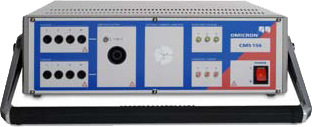
OMICRON CMS 156
General Specifications -
| Voltage Amplification |
|
|
|
|
|
|
|
|
| Current Amplification |
|
|
|
|
|
|
|
The following table describes of the two batteries that are used in the IDM+ device.
| Details | 4S2P5SWB-SB | NH2054 |
|---|---|---|
| Manufacturer | Rajaane telectric Private Limited | INSPIRED ENERGY, INC |
| Part Number/Reference | 4S2P5SWB-SB-002 | NH2054HD24 |
| Battery Specification | ||
| Rated Capacity | 3.9Ah with 0.5 C Charging and 0.5C Discharging | 4.8Ah |
| Operating Environment | ||
| Charging | 0°C – +45°C, Maximum 90% RH | 0°C to 45°C, <= 80% RH |
| Discharging | -20°C ~ +60°C, Maximum 90% RH | -10°C to 50°C, <= 80% RH |
| Storage Environment | ||
| Short Period less than 1 month | -20°C ~ +45°C, Maximum 90% RH | -20°C ~ +60°C<= 80% RH |
| Long Period more than 3 months | -10°C ~ +30°C, Maximum 90% RH | -20°C ~ +60°C<= 80% RH |
| Recommended storage | +15°C ~ +35°C, Maximum 85% RH | <21°C |
1. Physical Details -
| Devices | Physical Dimensions | Net Weight (Approx.) | Gross Weight (Approx.) |
|---|---|---|---|
| IDM + 3U Device | 487 mm wide, 132.5 mm high, 362.2 mm deep | 15 kg without battery, 15.5 kg with battery | 15 kg without battery and 15.5 kg with battery; Includes packaging and accessories if any. |
| IDM + 6U Device | 487 mm wide, 265.8 mm high, 362.2 mm deep | 23 kg without any external battery, 24 kg with two external batteries | 25 kg without battery and 26 kg with battery; Includes packaging and accessories if any. |
2. Front Panel Description -
| Label | Name | Description |
|---|---|---|
| 1. | LED Indicators | Status is configured to indicate different alarm conditions. |
| 2. | LCD Display | Used to display the information related to the device. |
| 3. | Keypad | Used to navigate. |