The analysis of an electrical system is done by mathematically modeling the system and solving them in finite time step to study the behavior of the system with various stimuli. The electrical power system is a highly nonlinear and dynamical system consisting of a large number of Differential and Algebraic Equations (DAE). These large numbers of DAE are solved for each time step and the overall states of the system evolve with time. The system is subjected to various stimuli in the form of parameter variation to the DAE at particular instant of time. The stimuli to the system are generally actuated by the controllers, which are also modeled mathematically.
The traditional simulation of electrical system is performed in a digital computer in which the system and the controller are solved in each time step. The actual time taken by the digital computer to perform a single time step of the simulation varies depending on the complexity of the DAE of the system, the duration of the simulation time step and the available computational resources. The system having large number of DAE takes more time to simulate a finite time step than the less complex system. The time of the actuation of the controller stimulus is managed exactly by the software framework of the simulation program irrespective of the actual time taken by the digital computer to simulate the system for the single time step.
More recently, the requirements are developed to validate a physical hardware controllers with the simulation model instead of a controller model used in the simulation as a part of more rigorous testing of a prototype controller before deploying to a practical system. The digital computer running a simulation is incapable to apply an actuation signal from a physical controller at an exact time as the time taken by the digital computer to simulate a fixed duration is not definite on each run. This is largely due to the non-real time operating system which runs user application at lower priority level and is superseded by system process when required. This mechanism of handling user application led to intermittent delay in the simulation process. As a result, the physical controller which actuates a signal assuming the system reached a specific state is mostly time skewed and the system in the simulation is either lags or leads the required state
The solution to the problem is a digital computer which runs each time step of a system simulation within actual time of the simulation time step throughout the simulation process. The digital computer suited for such specialized application is called a Real Time Simulator running a Real Time Operating System to handle the user application in Real Time. The Real Time Simulator is equipped with special purpose analog and digital input output terminals to monitor and actuate any state of the system in physical environment. The hardware controller which receives states of the system from the analog and digital output terminals of the Real Time Simulator is processed to generate the actuation signal. The actuation signal generated by the physical controller is connected to the analog and digital input terminals of the Real Time Simulator to modify the parameters of the DAE to study various scenarios. The simulation software running in the Real Time Simulation applies the external signal from the physical controller at the exact time step. This framework of validating and interfacing hardware with the simulated system is performed by Real Time Digital Simulator (RTDS). The process flow of the Real Time Simulation is shown in the figure below.
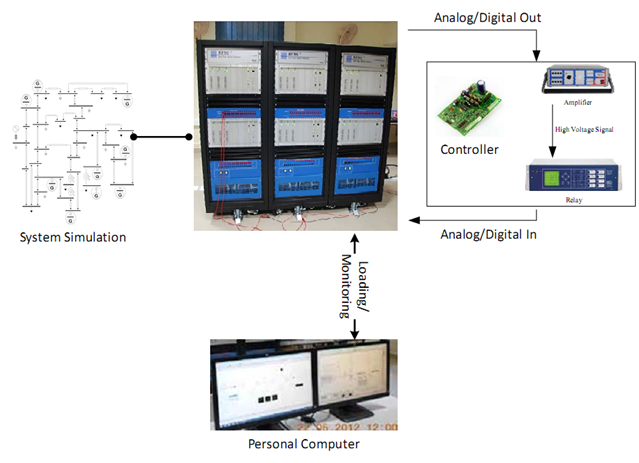
In IIT Kanpur, the efforts were taken to perform the hardware in the loop (HIL) testing for example testing the relay operation using the RTDS. The steps to perform Real Time Simulation are as follows:
- Build the system to be simulated in RSCAD Software in Personal Computer
- Connect the Hardware Controller (Relay) input with the required RTDS Analog/Digital output.
- Connect the RTDS Analog/Digital output to a power Amplifier if a physical relay is to be tested.
- Connect the Analog/Digital Output of the hardware Controller (the trip signal of the relay) with the Analog Digital input of the RTDS.
- Run the simulated system in RSCAD in the Personal Computer.
- Evaluate Results.
The power system is a highly nonlinear system that operates always in a changing environment. Power systems are subjected to different types of disturbances, small and large. Whenever power system subjects to a disturbance, system stability depends on the initial operating condition as well as the type of the disturbance. Formally, stability of the power system is defined as
“Power system stability is the ability of an electric power system, for a given initial operating condition, to regain a state of operating equilibrium after being subjected to a physical disturbance, with most system variables bounded so that practically the entire system remains intact ”
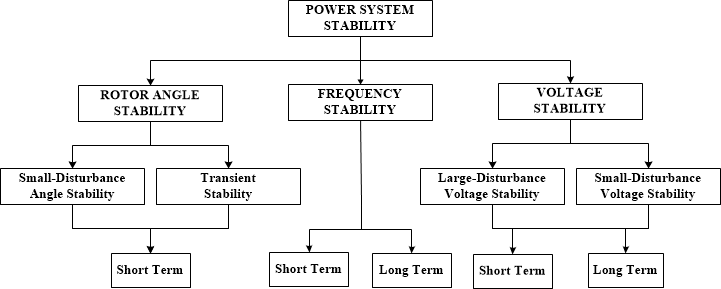
Basically power system stability is a single problem. However, the various forms of instabilities that a power system may undergo cannot be properly understood and effectively dealt with by treating it as a single problem. Due to high dimensionality and complexity of the stability problems, it helps to make simplifying assumptions to analyse specific types of problems using an appropriate analytical techniques. Analysis of stability, including identifying key factors that contribute to instability and developing methods to improve stability, is greatly facilitated by classification of the stability into appropriate categories.
Presently, department is carrying out active research in developing new algorithms for monitoring and control of power system stability. In particular, the work is more specific to angular stability and voltage stability. To study the performance of the newly developed algorithms, the real time digital simulation facility available at the institute is actively utilized.
There are two types of power system stability :
- Angular Stability
- Voltage Stability
Rotor Angle Stability:
Rotor angle stability is “the ability of synchronous machines of an interconnected power system to remain in synchronism after being subjected to a disturbance”. The stability depends on the ability to maintain/restore equilibrium between electromagnetic torque and mechanical torque of each synchronous machine in the system. The change in electromagnetic torque of a synchronous machine, following a perturbation, can be resolved into two components:
- Synchronizing torque component, in phase with rotor deviation
- Damping torque component, in phase with speed deviation
System stability depends on the existence of both components of torque for the each of the synchronous machines. Lack of sufficient “synchronizing torque” in synchronous machine may result in aperiodic or nonoscillatory instability, the lack of “damping torque” result in oscillatory instability. Further for gaining useful insight into the nature of instability problems, the rotor angle stability classified into two categories:
- Small disturbance or small signal rotor angle stability is “the ability of power system to maintain synchronism under small disturbance”. The disturbances are considered to be sufficiently small, such that the linearized system equations can be used for stability analysis. This type of instability further observed in two forms:
- Increase in rotor angle through a nonoscillatory or aperiodic mode due to lack of synchronizing torque.
- Rotor oscillations of increasing amplitude due to lack of sufficient damping torque. In the most of the power systems, small disturbance-rotor angle stability problem is usually associated with insufficient damping of oscillations. The periodic instability problem has been largely eliminated by the use of various control measures including continuously acting exciters. However, can still occur due to the action of excitation limiters (field current limiters). The oscillations caused by the small-disturbance rotor angle stability can be further classified into two major categories.
- Local plant mode of oscillations having frequency of oscillations usually in the range of 0.8-2.0 Hz.
- Inter-area modes of oscillations having frequency of oscillations usually in the range of 0.1-0.7 Hz.
In local mode of oscillations, a single power plant oscillates against the rest of the power system. The damping of these oscillations depends on the strength of the transmission system as seen by the power plant, generator excitation control systems and plant output. In Inter-area modes of oscillations, a group of generators in one area swinging against the group of generators in another area. The time frame of interest in small-disturbance stability studies in the order of 10-20 sec.
- Large disturbance rotor angle stability or transient stability is “the ability of the power system to maintain synchronism, when subjected to a severe disturbance, such as a short circuit on transmission line”. The resulting system response involves large excursions of generator rotor angles and is influenced by the non-linear power angle relationship. Transient stability depends on both the initial operating state of the system and the severity of the disturbance. The instability is usually in the form of aperiodic angular separation due to insufficient synchronizing torque, appearing as first swing instability. However, in the large power systems, transient instability may not always occur as first swing instability associated with single mode. It can be result of superposition of a slow-inter area swing mode, causing a large excursion of rotor angle beyond first swing. It could also be result of nonlinear effects causing single mode instability beyond the first swing. The phenomena transient instability usually observed in 3 to 5 seconds following the disturbance. It may extend to 10 to 20 seconds for very large systems with dominant inter area modes of oscillations.
Voltage Stability:
Power system is possibly one of the most complex man-made dynamical systems. Its stability and control have always been challenging task. Instability in a power system may be analyzed in different ways depending upon the system configuration, operating conditions and disturbances. With the development of improved control and protective devices like static VAR compensators, generator fast speed governing systems and voltage regulators, transient stability limits of power systems have increased considerably. The improvement in the transient stability limits allow more real power transfer over longer distances. Also due to economical, geographical and environmental reasons, the transmission and generation networks of the power system are being operated close to their maximum loadability limit. These factors have resulted in the increased reactive power demand in the system, leading to the difficulty of voltage control. This has contributed to the increasing number of voltage instability incidents worldwide that had led to the system voltage collapse.
Voltage stability can be defined as, “the ability of a power system to maintain steady acceptable voltages at all the buses in the system after being subjected to a disturbance from a given initial operating condition”.
The problem of voltage collapse may be caused by the inability of power system to supply the reactive power or by an excessive absorption of reactive power in the system. The nature of loads also plays an important role in deciding the final state of the system. Other factors that strongly influence voltage instability and collapse include transformer On-Load Tap Changer (OLTC) dynamics and generator exciter current limits. To prevent the system from going into the state of voltage instability, it is required to know the closeness of a particular operating point to the point of voltage instability or stability boundary. In most of the incidences of voltage instability, which occurred worldwide, voltage collapse occurred after several minutes of initiation of the disturbance. Hence, most of the studies have considered the voltage stability as a static phenomenon.
A number of methods for the voltage stability and voltage collapse prediction using conventional SCADA measurements have been proposed in the literature. However, it is difficult to implement the SCADA measurements based methods in real time, as they take significant time to execute.
With the development of the synchronized phasor measurements using Phasor Measurement Units (PMUs), it has become possible to build Wide Area Monitoring Systems (WAMS) and Wide Area Control Systems (WACS). The phasor measurement based voltage instability monitoring methods can be classified broadly into two categories, a) Local phasor measurement based methods and b) Global phasor measurements based methods. The local phasor measurements based methods mainly use the Thevenin equivalent concept in the prediction of voltage instability. Whereas, the global phasor measurements based methods give the wide area picture of the voltage stability. Global phasor measurements based methods require system wide measurements to implement the algorithms.
Presently, we have taken up active research in developing algorithms to monitor the voltage stability limits and also to develop methods to improve the voltage stability of the system using synchrophasor measurements. Voltage stability monitoring using real time digital simulation facility is presented below.
Voltage Stability Monitoring using Real Time Digital Simulation Facility [1]