Atmospheric Combustion Rig
Specifications
Current research
Past research
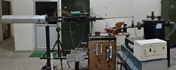
Combustion Tunnel
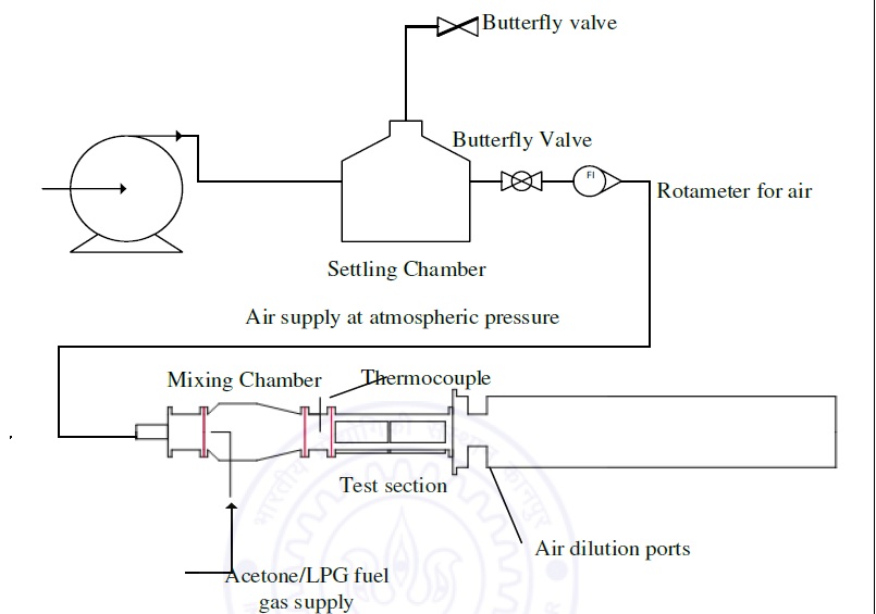
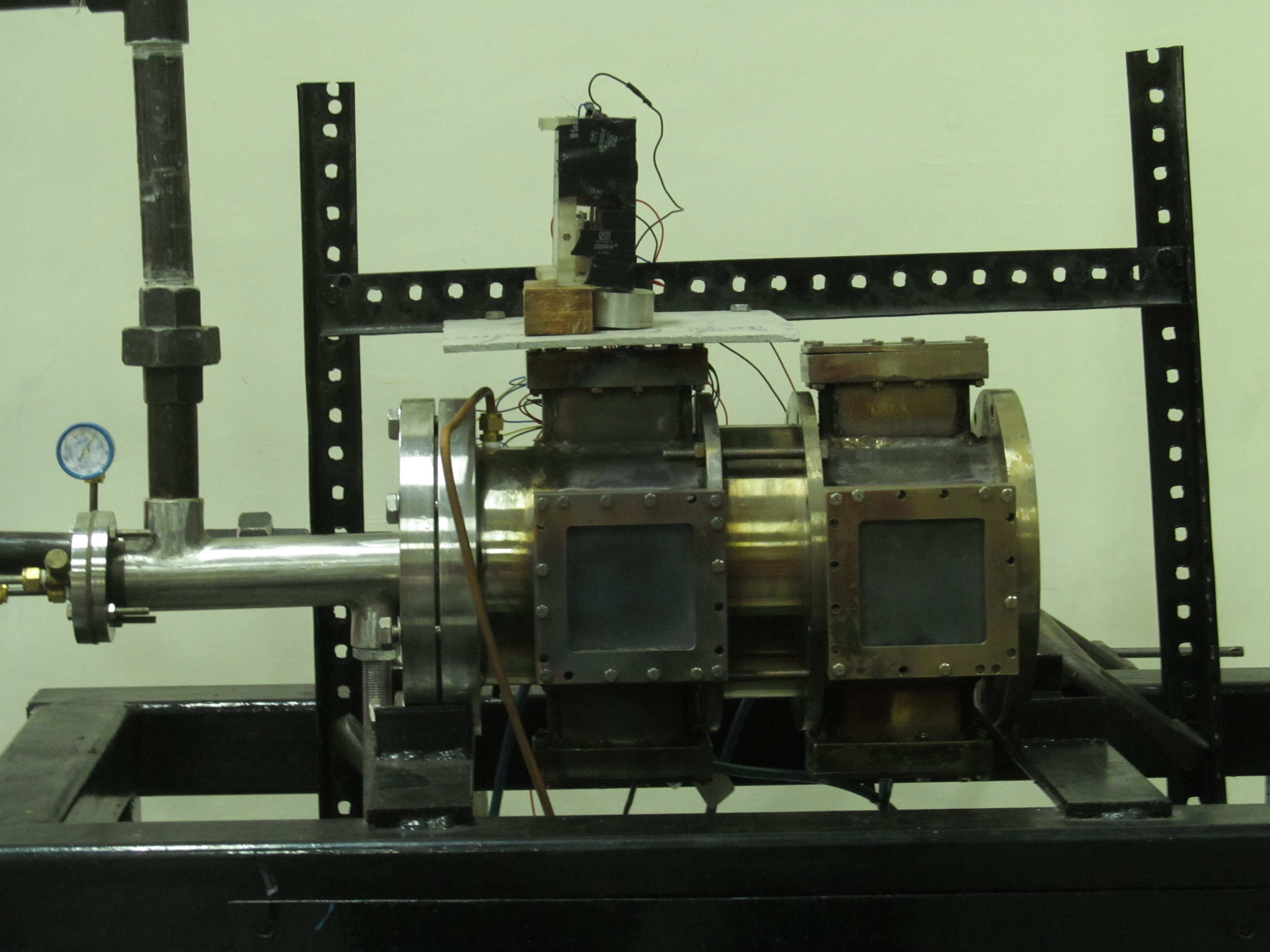
The experimental setup is designed for versatility and ease in conducting different types of combustion experiments. The setup is powered by an air blower providing air supply at atmospheric pressure through a by-pass in the chamber for controlling the air flow and also decoupling any external disturbances in the air from the experimental setup. The air then passes into a rectangular mixing chamber from the bypass chamber into a rotameter through a 4″ circular pipe and has a transition pipe to connect the circular pipe and rectangular duct. In the mixing chamber, the air mixes with the gaseous fuel, which comes from an angled pipe. The mixing chamber has a 2:1 contraction zone and a total length of 50 cm, which allows sufficient residence time for better fuel-air mixing. At the flanges, on both side of the mixing chamber, fine wire screens are used to prevent flashback and reduce large scale turbulence. Following the mixing chamber, a rectangular duct of cross section 10 cm x 8 cm, is used to straighten the flow. This duct has a K type thermocouple mounted into it, for measuring the test section inlet temperature. The mixture then flows into the test section through a metal plate which has a slit of required shape and area of 4 cm2 to allow the flow. This metal plate has a fine wire mesh welded onto it to prevent flashback. Test section is 30 cm long and has three optical windows made with quartz for optical diagnosis. Following the test section is a long circular exhaust pipe, which decouples the setup from external disturbances and has large air dilution ports to avoid overheating.
Specifications
Mass Flow Rate of Air: 20 – 200 LPM at NTP
Flow rate of Fuel: 0.1 – 10 LPM
Inlet Area: 4 cm2
Range of Combustion chamber velocities: 1 – 8 m/s
Instruments and Measurement Techniques: Rotameters for flow rate, K-type thermocouple of temperature. Shadowgraphy, PLIF and High speed imaging optical techniques
Completed Research
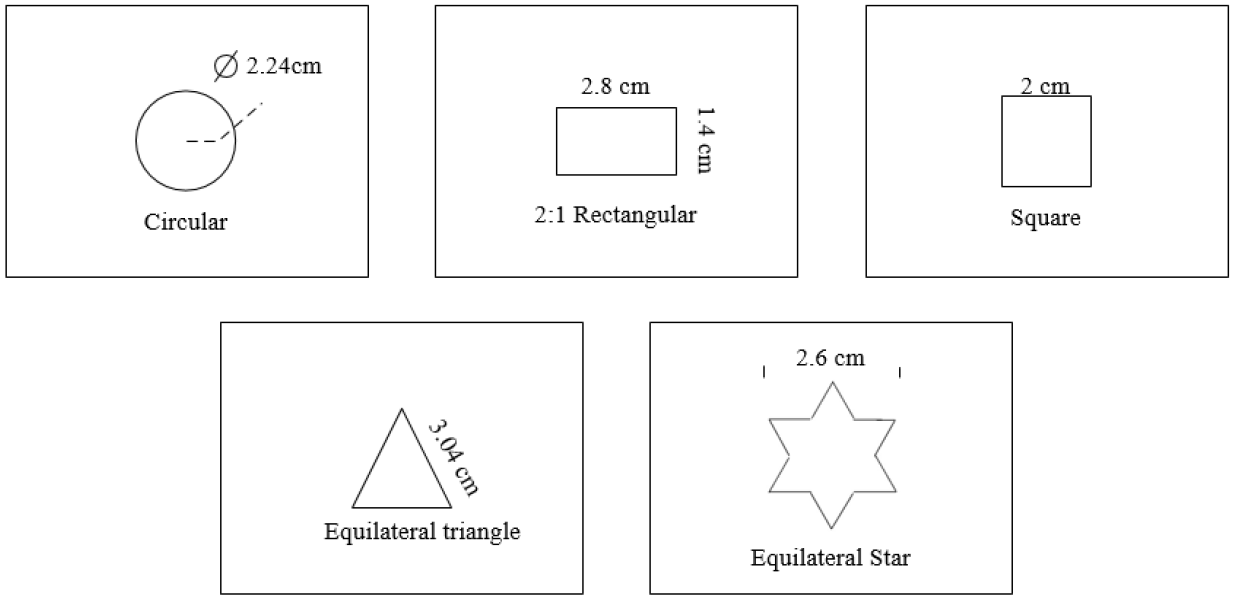
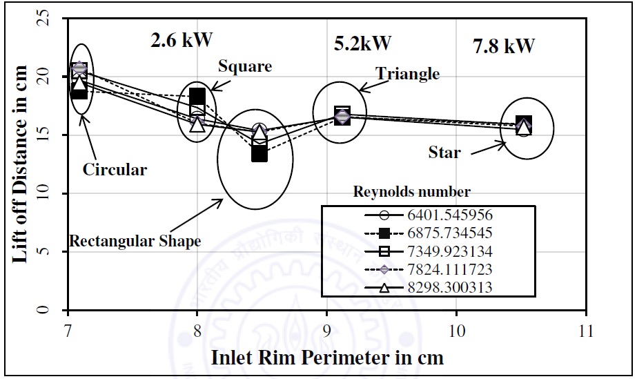
Comparative study of Dump Combustor with Non-Circular Inlets: Different inlet geometries are compared to find which is most effective in improving combustion issues in a lean premixed dump combustor. Also, the effect of different geometric parameters like perimeter, number of corners, elongation effect and symmetry are studied, to determine which of these parameters are most dominating and what happens if we do not use them. LPG is used as the fuel.
Future Research
Effect of reactive combustion gases on film cooling, with applications in high pressure turbine (HPT) blades.