CHAPTER 4
DIMENSIONAL CONTROL
4.1 Introduction
Total quality control aims to ensure that all the subsystems of a system have dimensions within the specified tolerances. It is both cost effective as well as quick if this can be checked while the sub-systems are being manufactured. Lasers can be used for checking the dimensional tolerances with great speed and accuracy, many times ‘ on-line ‘. Checking of dimensional tolerance involves the precise measurement of distance and laser techniques have potential of measuring distance to an accuracy of the wavelength of light making them the best devices for dimensional control. Laser based dimensional control techniques find applications in a wide range of products like sheet thickness of plastics, rubber and metals, dimensions of piston rings, cylindrical heads, sparks plugs, fuel injector components and choke springs, wall thickness of tube and hoses etc. The list is indicative of the enormous diversity of products where laser based system can be used to check the dimensions of the products. Hence, it is not possible to describe a generalized system. Some of the systems developed to meet the specialized nature of specific applications are summarized in the following sections.
4.2.1 Measurement of Small Dimensions Using Diffraction
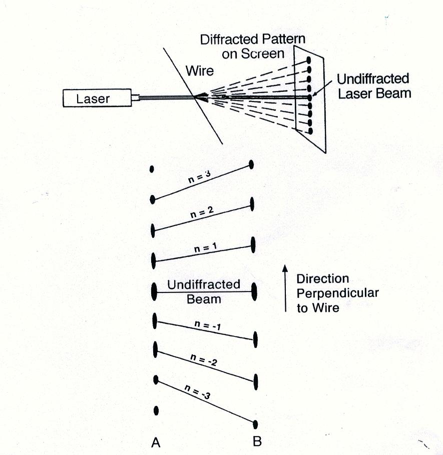
A specific example of this technique is the monitoring of diameter of a wire or fiber. The diameter is monitored at the preparation stage and immediate corrective procedures can be initiated as and when the wire diameter is not as per specification. In this technique wire/fiber is inserted in the path of a laser beam ( Fig. 4.1). Diffracted spots are projected on a screen and diameter D of a wire/fiber is given by
sinj n = nl / D
Where j n is the angle of the nth spot from the direction of the laser beam and n = 1,2,3,4, - - - - -. An automated detection system consisting of an array of photodiodes or a vidicon is used to detect the diffraction pattern. The output from the detector is analyzed by a computer to give direct read out of the wire diameter. Diameters of wire/fibers of the order of 0.00025 cm can be checked to an accuracy of 0.5%.
Same technique can be used to check the width of manufactured parts, thickness of plastic/rubber/paper sheets, flatness of steel position rings and dimensions of small gaps like tape heads and sparks plugs. The technique is highly sensitive to small changes in the dimensions as is obvious from the equation.
4.2.2 Triangulation
In optical trigulation,light from a He – Ne / diode laser is made to fall on a diffusive surface and the scattered light from the surface is focused on a position sensitive detector like an array of photodiodes. Thus any displacement of the scattering surface can be detected. Setup to detect one dimensional displacement is shown in Fig. 4.2 ,D z is given by
D z’ = m ( sinq / sinj ) D z
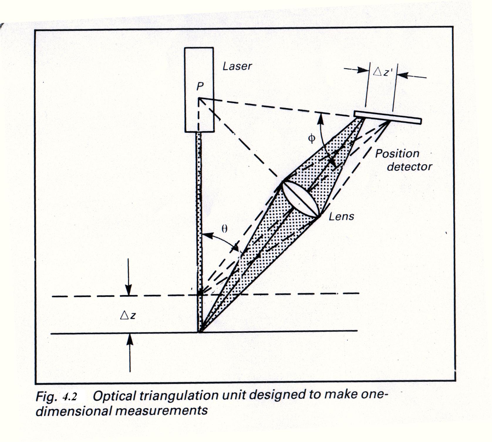
In order to detect displacement in two dimensions a setup shown in Fig. 4.3 is used. In this setup we have
x ‘ = m D x and D z ‘ = m (sinq / sinj ) D z
The detector output can be fed to a computer for direct display of the displacement. The technique is useful to check the dimensions of the seams and gaps in sheet metal and contours of manufactured parts.

4.2.3 Gauging
This is an optical micrometer in which (Fig. 4.4) a laser beam falls an a rotating polygon mirror and the rotating laser beam is collimated by a lens. The beam exiting the lens scans across a plane parallel to the lens axis at a speed given by
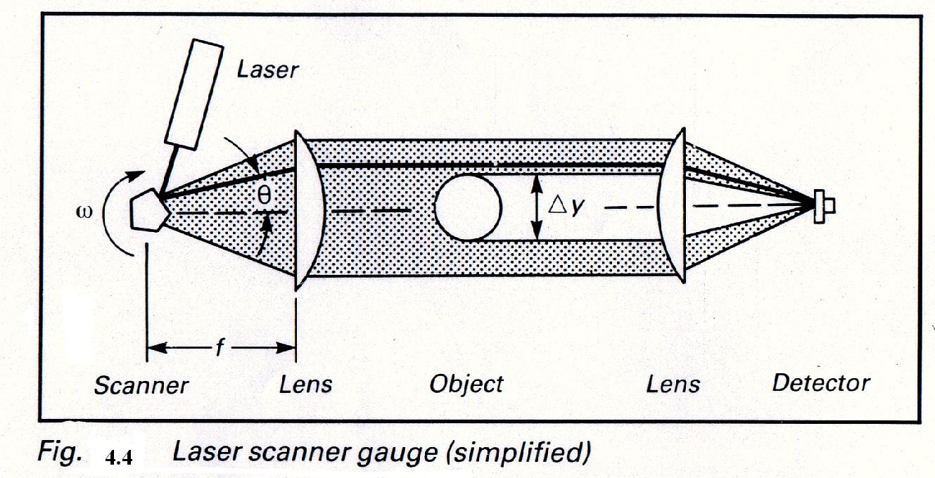
V = 2wf
where f is the focal lengthof the lens and w is the speed of rotation of polygon mirror. An object placed in the scan plane (Fig. 4.4) will block the beam for a time period D t. The dimension D y is given by
D y = V D t = 2 w f D T
A second lens is used to focus the beam on a photodiode and output of a photodiode is given to a computer for data processing. This technique can be used to check the diameter of wires and cylindrical shafts while in production so that feedback can be provided to compensate for process variations.
4.2.4 Two Spot Method to Measure Surface Displacement
In this technique a laser beam is divided in two beams so that two spots are formed on the surface under investigation. The scattered light from the surface is focused on a linear photodiode array. The photodiode array output is fed to a computer for data processing. When the surface is at the required position (reference position), both the beams fall on the same spot on it and detector gives one output. If the surface moves away from the reference position, two spots are made on the surface and detector produces two outputs. The distances between the two spots on the surface is measure of the displacement (D) of the surface. The two are related by (Fig. 4.5)
S = 2 D / tanq
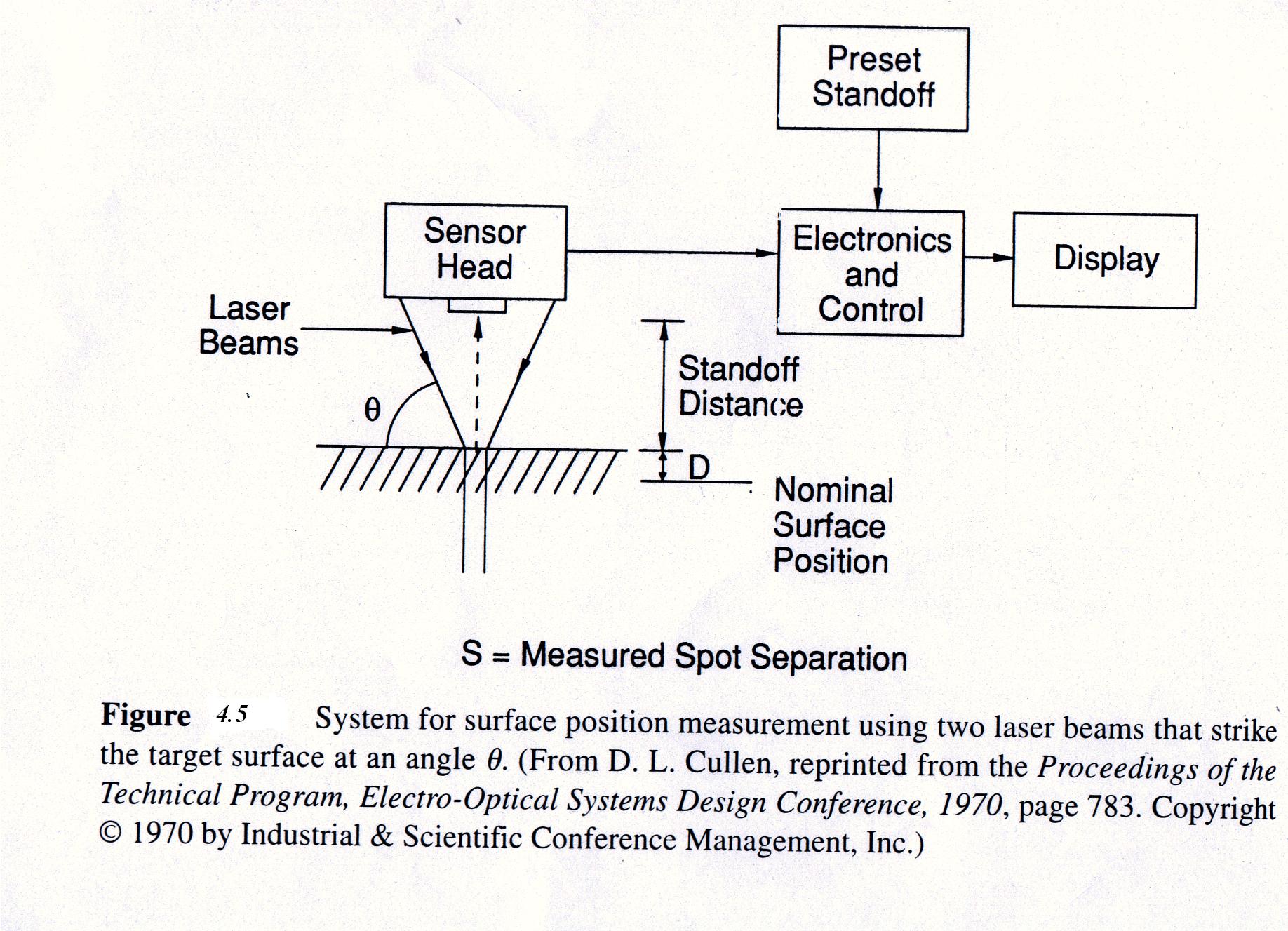
This technique is useful to check the gaps and the uniformity of the sheets. This technique is able to provide an accuracy of 0.0003 inch over a dynamic range of 0.2 inch with response time of about 1ms.
5.2.5 Measurement of Particle Size DistributionDetermination of particle size is very important to check the quality of products like polymers, abrasives, inks, tires, food products etc. Laser based technique available to determine the particle size distribution are remote, non-contact, rapid and simple, particularly, when the particle sizes are larger than the laser wavelength. In this technique, the beam from a He – Ne/diode laser is expanded and transmitted through the sample containing the particles. The scattered light is collected by a lens and focused onto an array of detectors. Light that was not scattered is focused on the central axis of the system, while the light scattered at small angles is focused off – axis, with distance from the axis increasing as the scattering angle increases. The particle size distribution is obtained by the angle is of relative signals from detectors at different distances. Varity of laser-based instruments to check the particle size distribution are available commercially covering the range from 0.04 to 2000 mm in a single scan, within a time of a few tens of seconds.
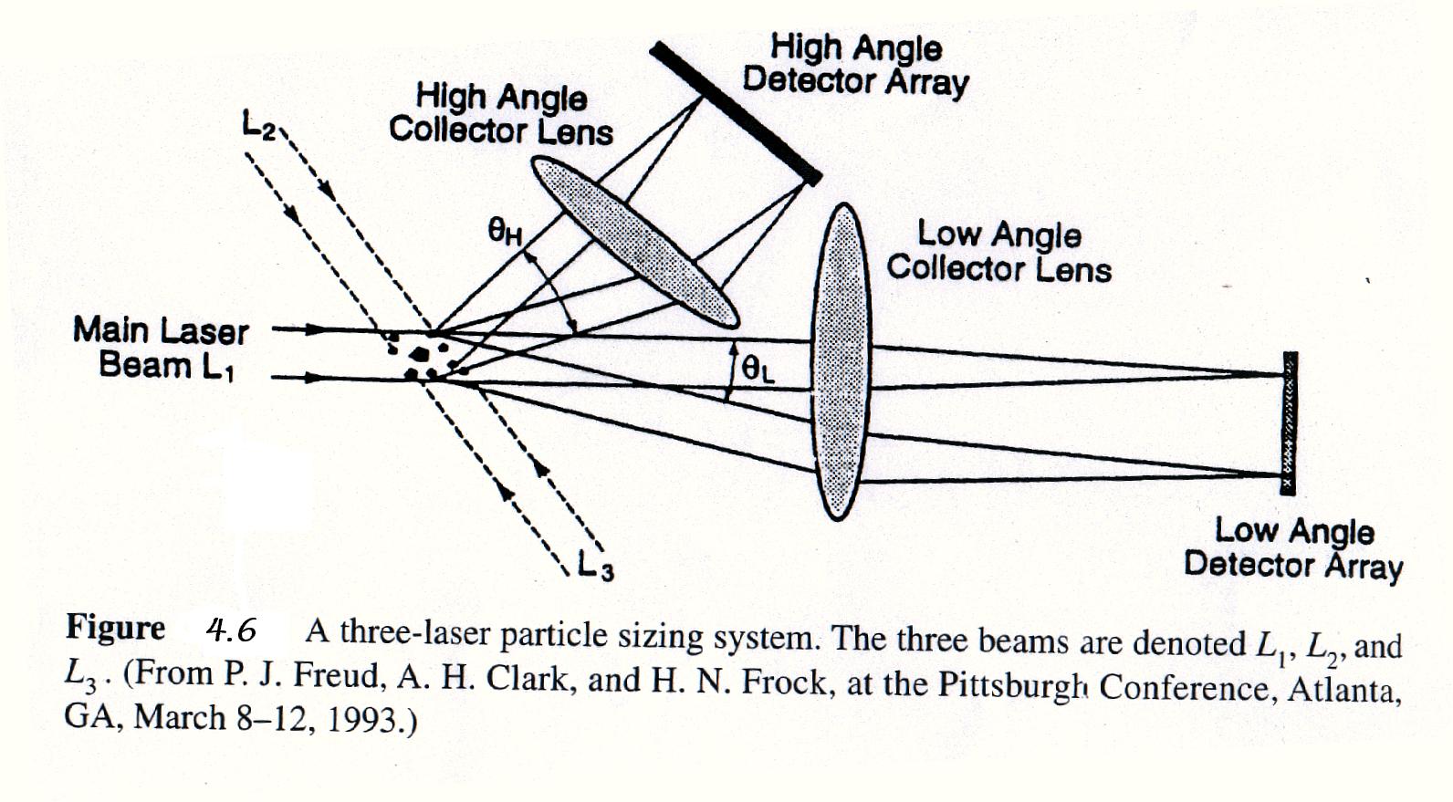
A typical laser-based particle size is shown in Fig. 4.6. It employs three diode laser beams L1, L2, L3, two detector arrays and two lasers. Light scattered from L1 (designated main beam) is detected by two photodiode arrays, one array with detectors at small angle to the beam while other array at an angle of about 60° . Light scattered from L2 is also detected by the some two arrays, but at scattering angles greater than 60° . Laser beam L3 is backscattered which is also detected by the same arrays. This configuration covers a size range 0.1 – 700 mm for both wet and dry particles.
4.2.6 Checking of Strain
Measurement of surface strain of a manufactured product is an important measurement to ensure the quality of the product. Laser based instrumentation to check surface strain is based on a phenomenon called speckle pattern. Laser light reflected from a diffusive surface appears to be mode up closely spaced bright and dark speckle spots due to constructive and destructive interference of light reflected from small peaks and valleys on the surface. The speckle pattern can be recorded using a two-dimensional photodiode array. To check the surface strain, a beam from a He – Ne laser is split into two parts and the resulting beams are made to incident on the same spot on the test surface. The two beams are switched ‘ on ‘ and ‘ off ‘ sequentially. The speckle patterns produced by two beams are recorded. The data is analyzed to get the surface strain. Resolution of the order of 0.3mm displacement resulting from strain is obtainable with this technique.
4.2.7 Checking the Roundness and Cylindricity
The degree of roundness and cylindricity can be checked using laser based grazing angle interferometry. In this interferometry a laser beam is incident on reflecting surfaces at an angle which is very close to 90° . The reflected beams are made to interfare. The grazing angle increases the sensitivity of the measurement by ( 1/cosq ) factor compared to normal incidence interferometry (Michelson interferometer). To check the roundness and cylindricity, light from a laser is split into two beams by a diffractive optical elememt in such a way so that one beam is incident on the surface of cylinder at an grazing angle The reflected beam from the cylinder is made to interfere with the other laser beam so as to produce interference fringes which can be analyzed to determine the departure from the desired shape. With this technique the roundness can be determined to within a fraction of a micrometer around the periphery of the cylinder.