
CHAPTER 5
DEFECT DETECTION
5.1 Introduction
Detection of flaws is perhaps the most important task of total quality control program because a very minor defect in a manufactured part (for example hair-line fracture in an aeroplane wing) can result in a disaster at a later stage. In its simplest form, the laser light is made to fall on the test surface and specular reflection from the surface is analyzed for defects. The sensitivity can be increased by orders of magnitude by combining the specularly reflected light from test surface with the portion of the light reflected from a standard surface so that an interference pattern is obtained. However, both these techniques are restricted to reflecting surfaces. Defects in surfaces that do not reflect specularly can be determined using holographic interferometry, in which surface information is available in the form of holograms. All these three laser based techniques for defect detection are discussed in the following sections.
5.2 Laser scanner flaw detector
This technique is based on the fact that the amount of light reflected by a defective area of a surface is different compared to the light reflected by non-defective portion of the surface. A simple surface inspection system is shown in Fig. 5.1 . In this system, laser beam is made to fall on a rotating mirror placed at a focal point of a converging lens. This arrangement produces a scanning laser beam which remains parallel to the lens axis. The scanning laser beam is made to fall on test surface. The reflected light from the test surface is focused on to a detector. When the scanning beam passes over the defect, there is absorption resulting in less amount of reflected light. So intensity of reflected light is low from a defect compared to that from a good surface. The detector output is fed to the computer for analysis.
In the setup shown in Fig. 5.1, one can monitor scattered light instead of speculaly reflected light for detection of defects. The intensity of the scattered light from a defect is more than that of light scattered by non-defective portion of the surface. Thus a detector set to monitor the scattered light will detect very little light as the beam scans a defect. This technique is quit useful for mirror-like sufaces. To scan the entire surface with setup shown in Fig. 5.1, one has to move the surface.
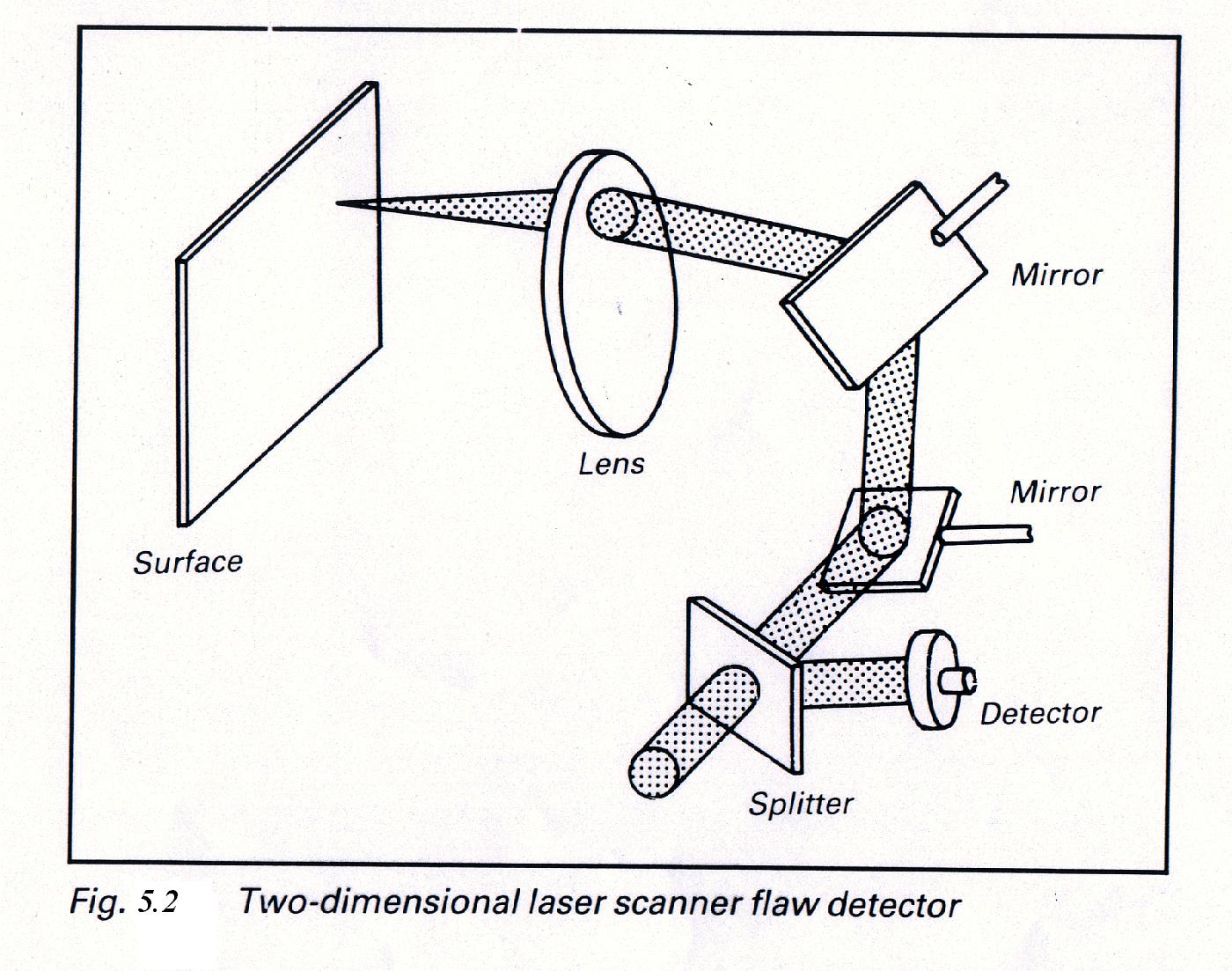
Alternatively, one can use two rotating mirrors (Fig. 5.2) so that beam can be scanned in a plane. In this case the reflected light is received back through the converging lens and is directed by a beam splitter to a to a detector for analyses. A specific example of this technique is the inspection of small caliber ammunition. A He–Ne laser beam is spread into a line with cylindrical optics and the structured light is made to illuminate a spinning catridge case, such that entire case gets illuminated. A fiber optic bundle placed off axis from the specularly reflected light, collects the scattered light from the caridge case. The scattered light spectrum is compared with a standard. The complete system is automated so that one can test 1200 cases/ min- not possible by non-laser techniques.
5.3 Interferometer Technique
In this technique, laser light is split into two beams. One of the beams is made to fall on the test surface, while the other is incident on a standard surface. The light beams reflected specularly from both the surfaces are made to form an interference pattern. Since the light reflected from the surface contains information about the surface, the interference pattern contains information about the surface. A solid state detector is used to detect the interference pattern and a computer is used to get information about the surface. Alternately, laser light is delivered to the surface through an optical fiber. The interference occurs between light partially reflected back from the top of fiber and light reflected from the surface under test. As the beam is scanned over the surface, variations in surface conditions lead to changes in the interference pattern, which can be processed to determine the surface conditions. A very fine laterial resolution can be obtained by this technique. Many instruments based on the interferometric technique for flaw detection are available commercially. These instruments rely heavily on computer processing. The measurements can be done in a few seconds with vertical resolution of the order of subnanometers and horizontal resolution of a few micrometers. These find wide ranging applications in solid state electronic circuitry.
5.4 Holographic interferometery
Holography is a technique of recording a 3-dimensional image (hologram) of an object. One can record a hologram of a manufactured object, subject it to the strain the object is expected to with-stand and then record the hologram of the part after the strain is removed. Both the holograms on reconstruction produce the images of the object before and after it is strained. Light from the two images can be made to interfere. The interference pattern thus obtained contains the inferomation about the effect of strain on the object. Any week area or defect in the object can be easily detected. This holographic interferometric technique of defect detection is highly sensitive and can be used in a verity of applications. Before discussing the technique let us briefly discuss the recording of a hologram.
5.4.1 Holography
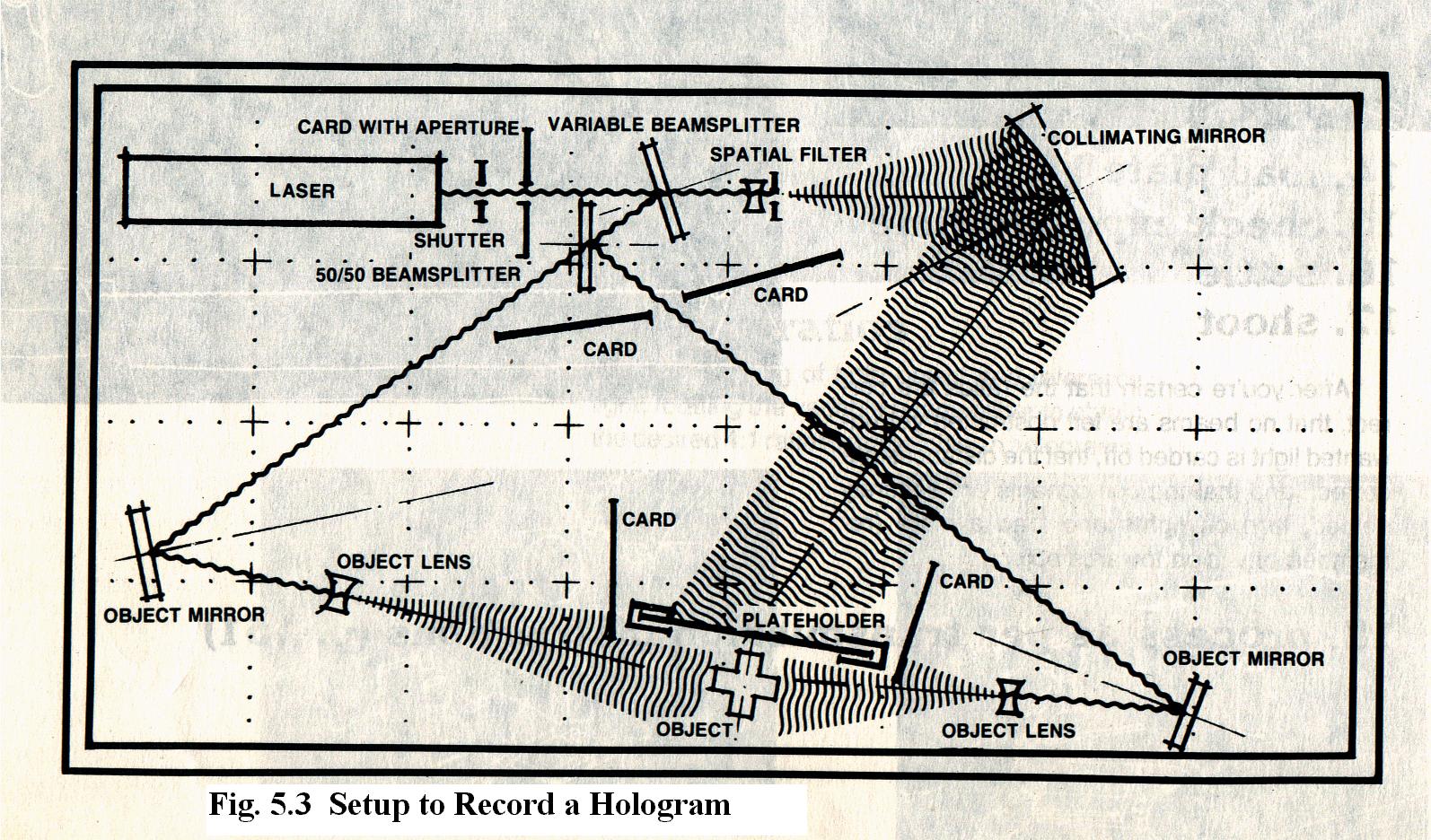
A 3-D image can be stored using holographic techniques. Laser beam (Fig. 5.3) is divided into two beams, reference beam and object beam. The reference beam is made to fall on a photographic plate, while object beam illuminates on object. The light scattered from the object is also made to fall on the photographic plate, where an interference pattern is formed due to reference beam and the scattered light. The photographic plate is processed. This is called a hologram and it has 3-D image of the object stored in it. To view the image the hologram is illuminated using a laser of the same wavelength as that of the laser used for making the hologram. The light diffracted by the recorded interference fringes form a 3-D image of the object in the same position occupied when the hologram was recorded.
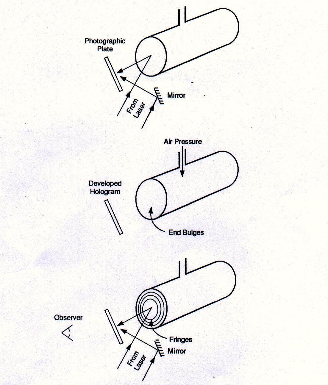
5.4.2 Real-Time Holographic interferometry
The steps involved in this technique are:
5.4.3 Double-exposure holographic interferometry
In this technique, holograms of the test object is made before an object is strained ( or used) and after it is strained (or used). Both the holograms are then illuminated to see the fringe pattern which is interpreted in terms of the deformation in the test object. This technique is very simple but less versatile as it compares the original object with only one altered state of the object.
5.4.4 Time-average holographie interferometry
This technique is useful to check the quality of vibrating objects like musical instruments, turbine blades, air-craft parts, engines, frames, brake system etc. The hologram of a vibrating system is recorded. This hologram is similar to a double- exposure holographic interferogram, in which two different exposures represent the positions where the surface spends the most time. These two positions are the positions of extreme displacement of the surface (Fig. 5.6).
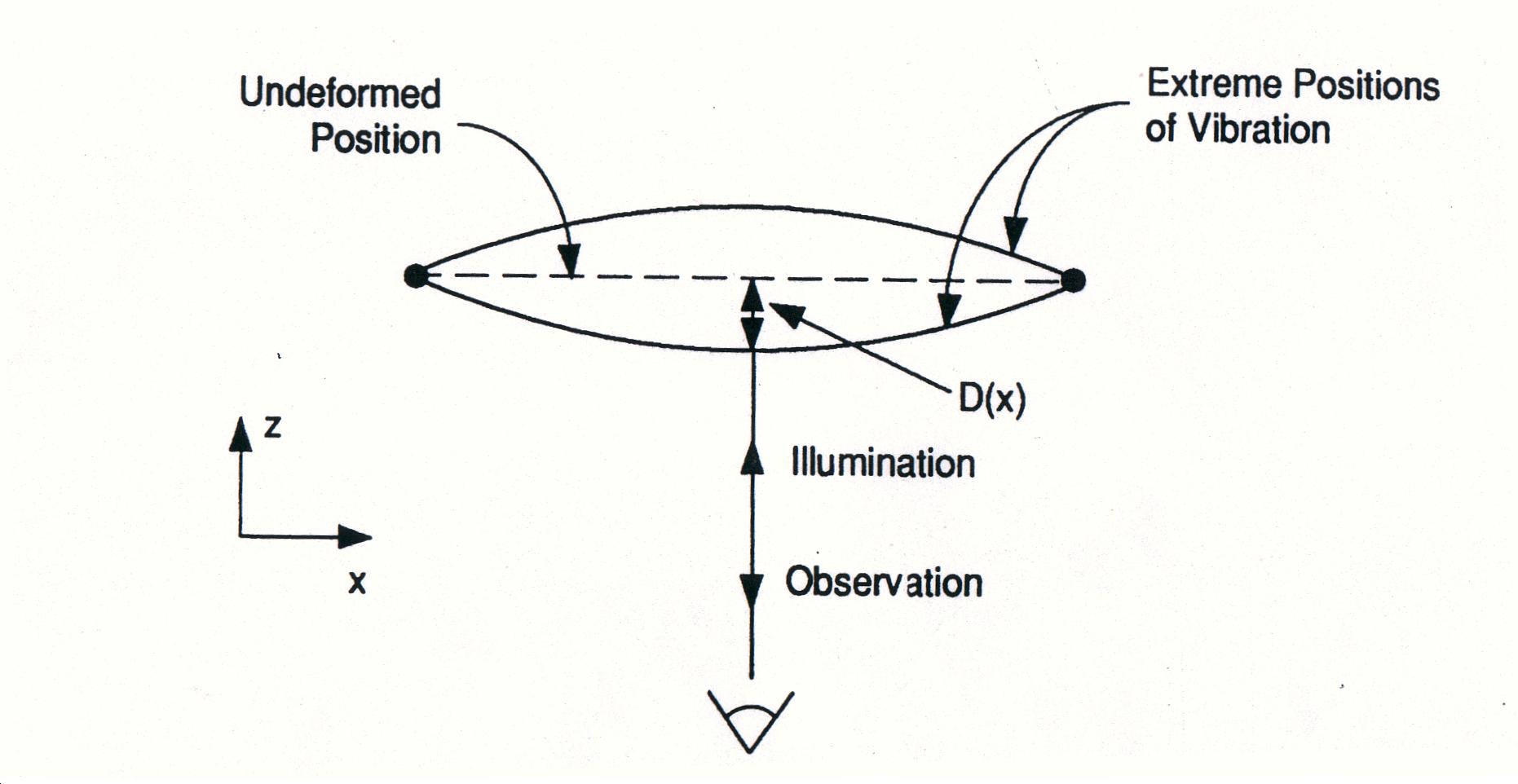
I(x) = {l / 4 p D(x) } cos2[4p D(x)/l - p /4]
D(x) is the displacement of surface from undeformed/equilibrium position. This equation is used to analyze the fringe pattern to obtain maximum amplitude as function of position across the surface.